

This guide shows a practical, repeatable workflow for 3D relief (embossed) laser engraving on metal using GWEIKE Cloud software with a GWEIKE G3 fiber laser engraver. If you have ever imported a 3D model and ended up with stepped layers, grey surfaces, or misaligned engraving, this tutorial is designed to fix that—by explaining both the click-by-click process and the settings logic.
Recommended setup used in this tutorial
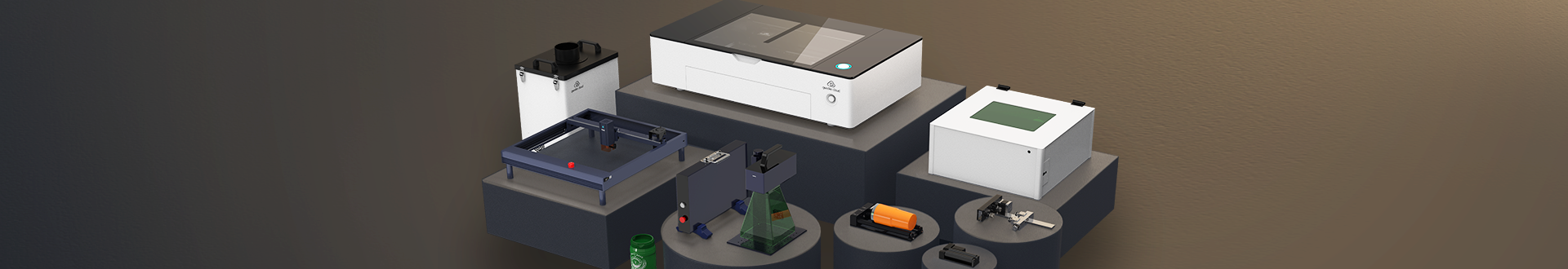
Machine GWEIKE G3 fiber laser engraver Software GWEIKE Cloud (3D Embossing / Relief mode) Files STL / OBJ / DEEP (and PNG for 2D→3D construction), GWEIKE G3 fiber laser engraver — G3 Basic (20–50W fiber + 20W diode)
If you are building a small production workflow for metal tags, badges, or coin-style pieces, the combination of a stable fiber source + a relief-capable software workflow is what makes the results reproducible.
What 3D relief laser engraving is
“3D laser engraving” is a broad term. In practice, it usually refers to one of these three categories:
A) 3D relief (surface) engraving
The laser removes material in multiple layers based on a height map from a 3D model (often STL/OBJ/DEEP). You get real surface depth: highlights, shadows, and tactile texture.
Typical outputs: metal badges, plaques, logos, coin-style reliefs, textured nameplates.
B) 3D crystal (subsurface) engraving
A specialized laser focuses points inside crystal/glass to create a “floating” 3D image. It is a different machine class and a different process.
Typical outputs: 3D photo crystals, gifts, memorial crystals.
C) “3D printer + laser engraver” combos
Many hobby systems add a laser module to a 3D printer frame for 2D engraving/cutting (and sometimes shallow shading). That workflow usually uses G-code, and it does not behave like a fiber-laser relief workflow on metal.
This guide focuses on Category A: relief/embossed engraving on metal using a fiber laser (GWEIKE G3) and a relief-capable workflow in GWEIKE Cloud.
What you need (metal, 3D files, and software)
Metal and surface preparation
Relief engraving is less forgiving than simple marking. The reason is cumulative heat and cumulative error: you are not doing one pass—you are doing many. A small setup mistake becomes visible after layers stack up.
- Flatness matters: if your metal is not flat, the effective focus changes across the job, and relief depth becomes uneven.
- Cleaning matters: oil, residue, or protective films can create uneven absorption and lead to grey/dirty surfaces.
- Finish matters: mirror-like surfaces can look great but are more sensitive to focus and post-cleaning.
3D laser engraving files: STL vs OBJ vs DEEP and what “good” looks like
Relief workflows typically accept STL, OBJ, and (in this mode) DEEP files. The bigger difference is the quality of the model itself:
- Polygon density: Low-poly models show faceting. In relief engraving, faceting becomes visible as angular highlights and “flat planes.”
- Reasonable depth range: Extremely deep models increase machining time and heat load. Start with shallow relief and scale up.
- Avoid needle-like peaks: Very sharp spikes can burn out or lose shape in metal relief because each layer erodes edges.
- Orientation matters: A model “leaning” can force uneven depth across the job.
If you are searching for 3D laser engraving files, look for models explicitly labeled “bas-relief,” “coin relief,” or “badge relief.” They are usually designed with depth and readability in mind.
3D laser engraving software: what features matter for relief
Not all engraving software can do true relief. For surface 3D relief, you want software that can:
- Import 3D models (STL/OBJ/DEEP)
- Generate layered toolpaths based on height (layers / depth slicing)
- Provide accurate preview/frame alignment tools
- Support a 2D-to-3D construction path when you don’t have a full 3D model (optional but useful)
In this tutorial, we use GWEIKE Cloud because it provides a relief/embossed workflow aligned with the GWEIKE G3 fiber platform.
GWEIKE Cloud UI map + supported formats
In the 3D Embossing/Relief screen, most controls are in the right-hand Settings panel. The demo explicitly shows supported formats and the core parameters you will adjust.
Supported formats (import)
- STL files
- OBJ files
- DEEP files
You can also start from an image (e.g., PNG) and build relief via 3D Construction.
Key parameters shown in the demo
- Z-axis movement (mm): 0.1 (Move up / Move down)
- Number of Layers: 256
- Power range (%): 75
- Speed (mm/s): 1000
- Frequency (KHz): 30
- DPI: 200
- Engrave Model Size: 1.00 (Model Scale 1)
2D image → 3D relief (3D Construction) values shown
The demo also shows an optional workflow where you import an image (example: horse.png) and build a relief using 3D Construction. The values displayed in the dialog are:
- X Length: 25.00
- Y Length: 25.00
- Z Length: 1.50
-
Contour Threshold: 5.000

Step-by-step workflow in GWEIKE Cloud (STL/OBJ/DEEP and optional 2D→3D)
If you skip the “small test” step, you can still succeed—but your risk of wasting material increases.
- Select Relief/Embossed Engraving mode. Relief engraving requires a mode that interprets height information. If you use a standard 2D engraving mode, you may only get outlines or shading—not real depth.
-
Import your model file (STL/OBJ/DEEP) — or start from an image.
- 3D import: select a supported 3D format (STL/OBJ/DEEP) and confirm it loads correctly.
-
Optional 2D→3D: import a PNG and use 3D Construction (X/Y/Z size + Contour Threshold) to build a relief.

- Orient the model using Top View (critical). Top View maps to the physical X/Y movement plane. Use it to confirm orientation, composition, and “reading direction” before you continue.
- Scale and position for readability. Relief is about highlights and shadow transitions. If you scale a detailed model too small, fine features collapse into noise.
- Set the work area and origin (alignment discipline). Relief engraving often runs longer than standard marking. A small misalignment is expensive.
-
Preview / frame the engraving area. The demo explicitly instructs: once parameters are set, click Preview and adjust the position.
Common mistake: People preview once, then adjust the model size/position and forget to preview again. In relief engraving, always preview after any scale/position change.
- Set relief parameters: Layers and Z adjustments. Use a safe baseline first. The demo uses Number of Layers = 256 and shows Z-axis movement (mm) = 0.1 for fine control.
- Set energy parameters: Power / Speed / Frequency (baseline). The demo baseline shows: Power 75%, Speed 1000 mm/s, Frequency 30 kHz, and Model Scale 1.
- Run a small test (mandatory for beginners). Relief jobs can be long. A 20–30 mm test piece saves hours and avoids scrapping your final part.
- Optional: add a Cleaning pass for contrast. After relief removal, a light cleaning pass can reduce oxidation tint and increase contrast, making the relief “pop.” This is optional and should be done conservatively to avoid rounding details.
Settings logic (Layers, Z-step, Power/Speed/Frequency)
Most relief engraving failures happen because people treat settings as isolated numbers. In reality, relief success comes from stable removal per layer plus controlled heat. The sections below explain how to think about each major parameter.
Layers: smoothness vs time
Layers is the number of depth slices used to approximate the 3D surface. More layers generally means smoother relief transitions, but longer engraving time. The demo baseline (256 layers) is a practical starting point.
Z-step / descent height (and Z-axis movement)
In many relief workflows, Z control shows up in two places:
- Z-step / descent height (depth slicing): controls how depth is distributed across layers.
- Z-axis movement (mm): fine adjustment control (demo shows 0.1 mm with Move up/Move down).
Power / Speed / Frequency: think energy-per-area, not isolated values
A useful mental model is energy per unit area:
- Power increases available energy (and removal potential).
- Speed changes how long the laser dwells on each point.
- Frequency changes pulse density and can influence edge behavior and heat accumulation.
Recommended tuning order (to avoid chasing your tail)
- Set speed first to control heat buildup.
- Adjust power second to hit removal/contrast targets.
- Fine-tune frequency last to improve edges and reduce unwanted tinting.
Cleaning pass: when it helps, and when it harms
A cleaning pass can reduce oxidation tint and improve contrast. Use it lightly to avoid rounding fine features.
Troubleshooting: common problems and quick fixes
Use this section as a diagnostic checklist. The fastest way to fix relief engraving is to identify the symptom and change one variable at a time.
Problem 1: The model imports “tilted” or the relief looks uneven
- Likely cause: Model orientation is not parallel to the work plane.
- Fix: Use Top View; reset rotations; ensure the relief face is flat to the plane before setting depth/layers.
Problem 2: Preview framing looks correct but the engraving is offset
- Likely cause: Origin mismatch or preview done before final scale/position adjustments.
- Fix: Preview after every position/scale change; verify origin method; confirm your fixture matches your chosen origin.
Problem 3: Visible stepping / layer lines on slopes
- Likely cause: Layers too low or depth steps too large.
- Fix: Increase Layers (start from 256 and go up); validate time vs quality on a small test.
Problem 4: Details are “washed out” or edges look rounded
- Likely cause: Too much energy per layer, or cleaning pass too aggressive.
- Fix: Increase speed; reduce power slightly; reduce cleaning intensity.
Problem 5: Surface looks grey/dirty after engraving
- Likely cause: Oxidation tint from heat, surface residue, or suboptimal energy distribution.
- Fix: Clean the metal first; increase speed; apply a light cleaning pass; avoid over-cleaning.
Problem 6: Relief depth is too shallow (no “3D pop”)
- Likely cause: Depth target too low or removal per layer insufficient.
- Fix: Increase depth gradually; adjust power slightly; keep speed stable; validate in steps.
Problem 7: Depth is inconsistent across the workpiece
- Likely cause: Workpiece not flat, focus height inconsistent, or fixture flex.
- Fix: Improve fixturing; confirm flatness; re-check focus; use consistent origin + preview routine.
Problem 8: Rough texture / burr-like edges
- Likely cause: Unstable removal due to overly aggressive per-layer energy or unsuitable frequency region.
- Fix: Increase speed slightly; reduce power; fine-tune frequency last.
Problem 9: Engraving takes “forever”
- Likely cause: Excessive Layers, too-small depth steps, or overly large model size.
- Fix: Reduce Layers modestly; keep depth steps conservative; validate the smallest readable size before scaling up.
Problem 10: Results vary from day to day
- Likely cause: Inconsistent preparation (cleaning, focus height, fixture position), not “random laser behavior.”
- Fix: Standardize: (1) cleaning routine, (2) focus/height routine, (3) origin selection, (4) preview step, (5) saved presets per material.
Beginner test plan (repeatable results you can scale)
If you want relief engraving to be a production capability (not a one-off experiment), treat the first week as a controlled test program. Here is a simple plan that works well with GWEIKE G3 + GWEIKE Cloud.
The 6-rule test plan
- Start small: 20–30 mm test piece or a small region of the model.
- Start shallow: first run at ~30–50% of target depth.
- Change one variable: adjust only one parameter per iteration (Layers, speed, power, frequency, DPI).
- Record everything: material finish, focus method, Layers, Z settings, power/speed/frequency, and notes on color/edge quality.
- Fix heat first: if you see black/grey haze, correct heat behavior before chasing more depth.
- Use cleaning lightly: multiple light passes are safer than one aggressive pass.
Once you have a stable baseline, save it as a preset for that material and finish. This is how relief becomes scalable.
Production note
If your goal is repeatable metal relief products (tags, plaques, coins), keep your workflow consistent: run relief jobs in GWEIKE Cloud with saved presets per material, and standardize the focus + origin + preview routine on your GWEIKE G3.
Consistency is the real “secret sauce” behind professional-looking relief engraving.
FAQ
Here it means 3D relief (surface) engraving—the laser removes material in layers based on a 3D model (STL/OBJ) to create real depth.
No. 3D crystal engraving is a subsurface process that creates points inside crystal/glass. Relief engraving removes material on the surface.
Both can work. The bigger factor is model quality (polygon density, reasonable depth, and a relief-friendly design). Choose the format your software imports cleanly and consistently.
Use enough layers to avoid visible stepping, but not so many that job time becomes impractical. Start with a mid value, then increase layers if you see stepping—especially on gentle slopes.
It controls how much depth each layer represents. Smaller Z-step is safer and smoother (but slower). Larger Z-step is faster but riskier for detail and edge stability.
Grey haze often comes from oxidation tint and heat accumulation. Increase speed, reduce power slightly, clean the material before engraving, and consider a light cleaning pass for contrast.
No. It helps when contrast is low or oxidation tint is visible, but it can remove fine details if too aggressive. Start light and validate.
Only if the software supports true 3D relief: STL/OBJ import, layered toolpath generation, and reliable preview/framing. In this guide, we show the workflow in GWEIKE Cloud paired with the GWEIKE G3 fiber platform.
Run a small test, then tune in this order: speed (heat), power (removal), frequency (edge behavior), and only then refine layers/Z-step for smoothness.
What to read next
This page focused on 3D relief (embossing) laser engraving. If you want to go deeper into engraving fundamentals, material selection, and ready-to-use settings, these pages will help:
- How to Use a Laser Engraver for Color Engraving on Stainless Steel — a practical, screenshot-based workflow for color-like engraving on stainless steel (prep, focus routine, and parameter logic).
- Laser Engraving vs Cutting vs Marking (Beginner’s Guide) — clear definitions and “which process should I use?” decision logic before you start dialing in settings.
- Fiber vs CO₂ Laser Engraving: Material Comparison — a material-first guide to choose the right laser type (fiber vs CO₂) and avoid “wrong machine for the job” mistakes.
- MDF Engraving Settings — practical starting settings and setup tips for cleaner MDF engraving results.
- GWEIKE G3 vs G3 Basic: Complete Buying Guide
- Acrylic Engraving Settings (80W vs 130W) — power-based settings guidance for acrylic, focused on clarity, frosting depth, and edge finish.
- Openpr article
